2.Installation
Warning
Before installing:
Read and understand the safety instructions related to the BIO Gripper.
Verify your package according to the Scope of delivery and your order info.
Have the required parts, equipment and tools listed in the requirements readily available.
Installing:
Satisfy the environmental conditions.
Do not operate the Gripper, or even turn on the power supply, before it is firmly anchored and the danger zone is cleared.
Caution the fingers of the gripper which may move and cause injury or damage.
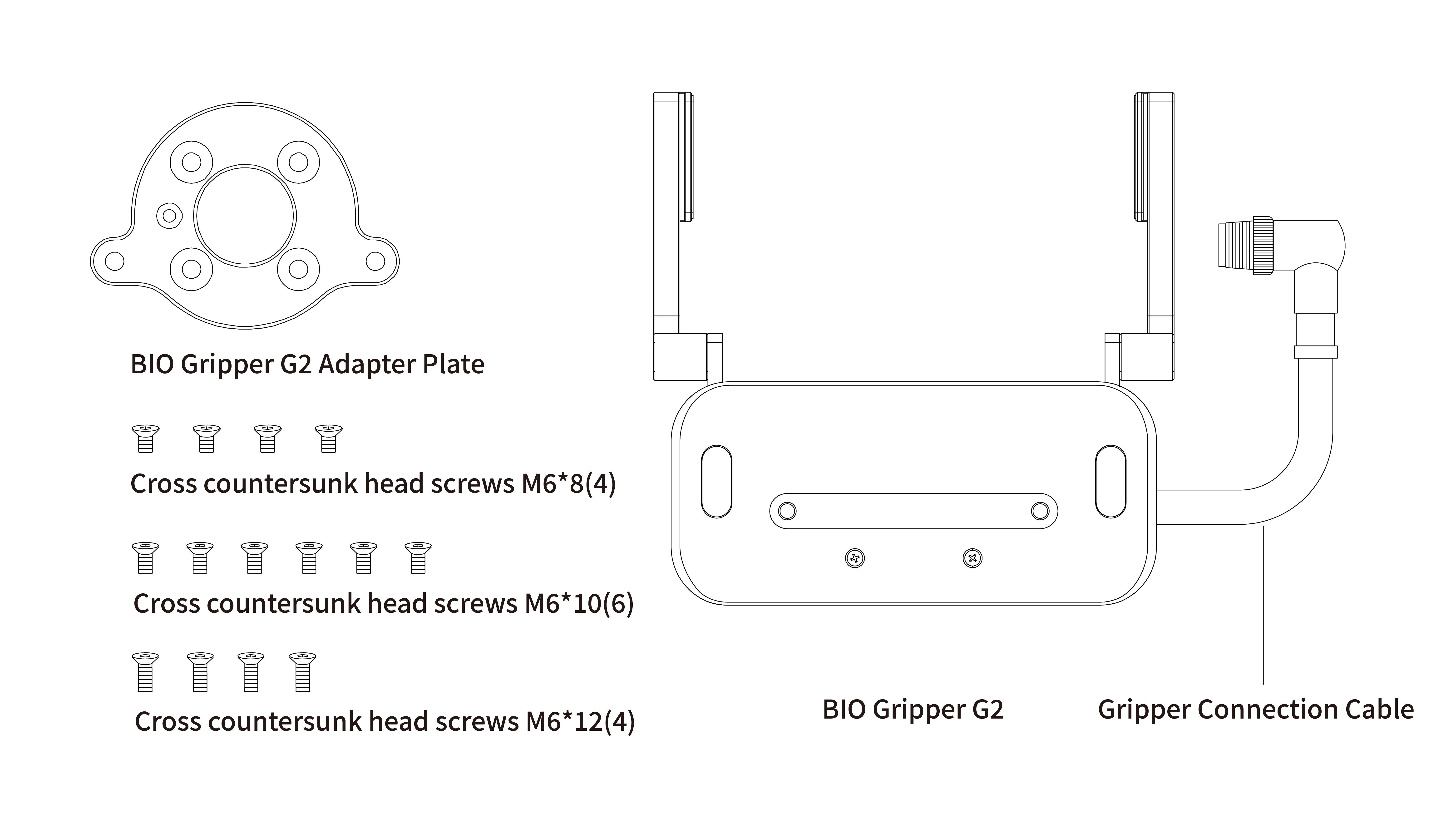
2.1 General Kit
A Gripper Kit generally includes these items:
- BIO Gripper G2(1)
- BIO Gripper G2 adapter plate(1)
- Cross countersunk head screws M6*8 (4)
- Cross countersunk head screws M6*10 (6)
- Cross countersunk head screws M6*12 (4)
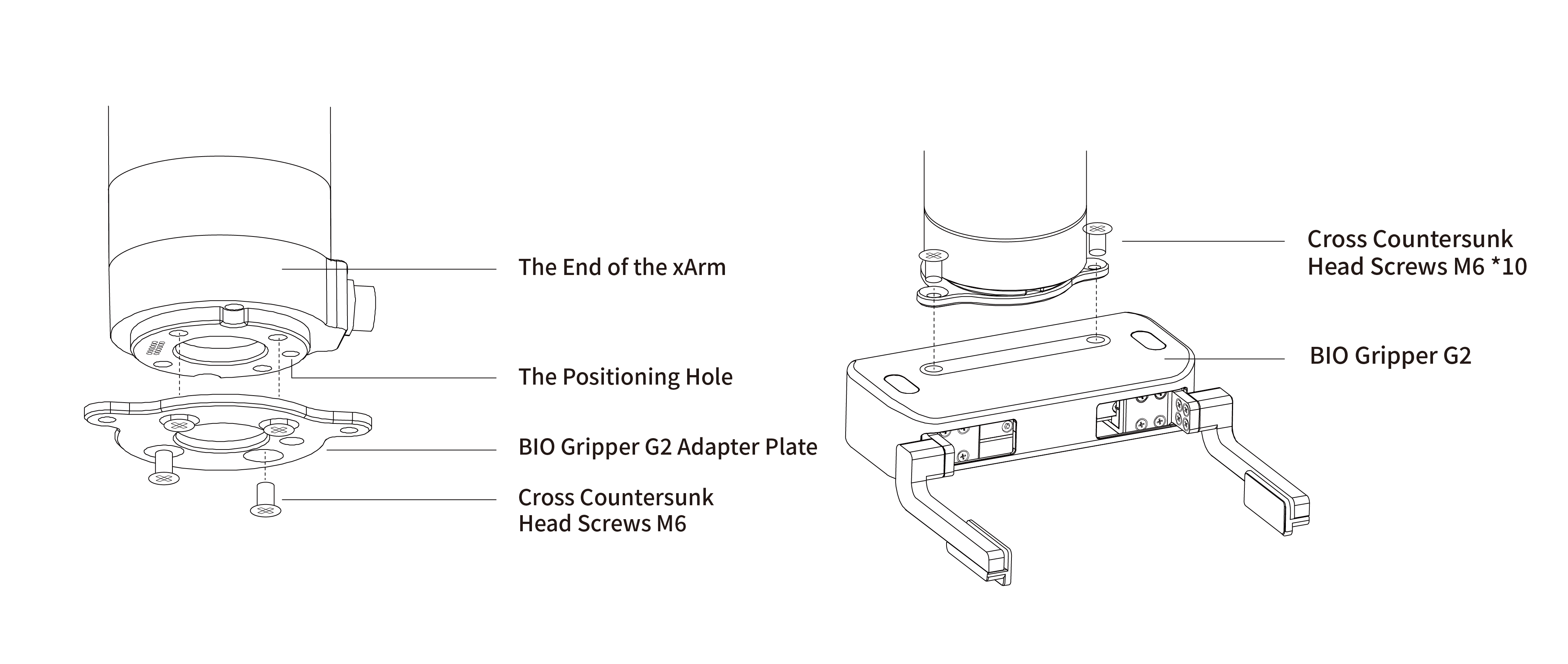
2.2 Mechanical Installation
BIO Gripper installation steps:
- Fix the BIO Gripper G2 adapter plate to the tool flange of the robotic arm with screws.
- Fix the BIO Gripper G2 to the BIO Gripper adapter plate with screws.
- Connect the robotic arm and the Gripper with the gripper connection cable.
Note:
When wiring the gripper connection cable, be sure to power off the robotic arm, the emergency stop button is in the pressed state and the power indicator of the robotic arm is off, so as to avoid robotic arm failure caused by hot plugging;
When connecting the gripper and the robotic arm, be sure to align the positioning holes at the ends of the gripper and the robotic arm. Since the male pins of the gripper connection cable are relatively thin, avoid bending the male pins during plugging.
2.3 Electrical Setup
Power and communication are established with the BIO Gripper via a single gripper connection cable. The gripper connection cable provides a 24V power supply to the Gripper and enables serial RS485 communication to the robot control box.
Warning
Power must be off before connecting the Gripper and the robotic arm via the gripper connection cable
2.3.1 Pinout Interface
The BIO Gripper is connected to the tool end of the robotic arm via a 12-pin connector.
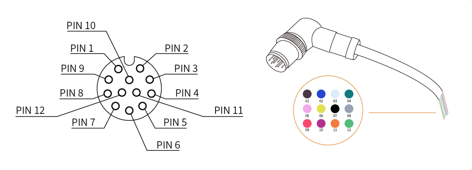
| Pin sequence | Function |
|---|---|
| 1 | 24V |
| 2 | 24V |
| 3 | GND |
| 4 | GND |
| 5 | 485-A |
| 6 | 485-B |
| 7 | Digital Input 0 |
| 8 | Digital Input 1 |
| 9 | Digital Output 0 |
| 10 | Digital Output 1 |
| 11 | No Connect |
| 12 | No Connect |
BIO Gripper G2 uses 24V (PIN1 and PIN2), GND (PIN3 and PIN4), 485A (PIN5), 485B (PIN6).
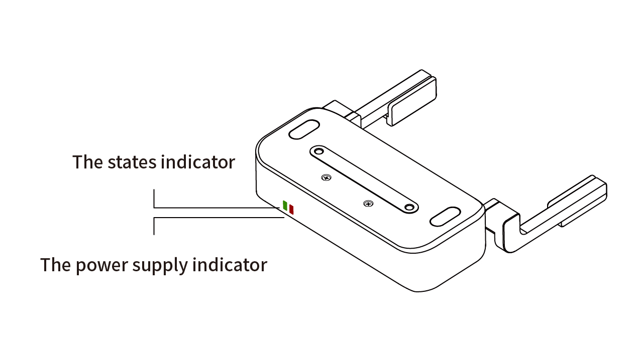
2.4 Indicator Lights
The BIO Gripper G2 provides 2 indicator lights, the power indicator and the status indicator.
- When the gripper is powered up, the power indicator light is always red and the status indicator light flashes green.
- When the gripper clamps something, the status indicator light is always on green.
- When there is an error in the gripper, the status indicator light flashes green rapidly.