2. Installation
WARNING
Before installation:
- Read and understand all safety instructions related to Gripper G2.
- Verify the package contents against the packing list and purchase order.
- Prepare all required parts listed in the requirements.
During installation:
- Meet the environmental conditions.
- Do not operate the gripper or power it on until it is securely mounted and the hazard area is cleared. The gripper fingers may move and cause injury or damage.
2.1. Packing List
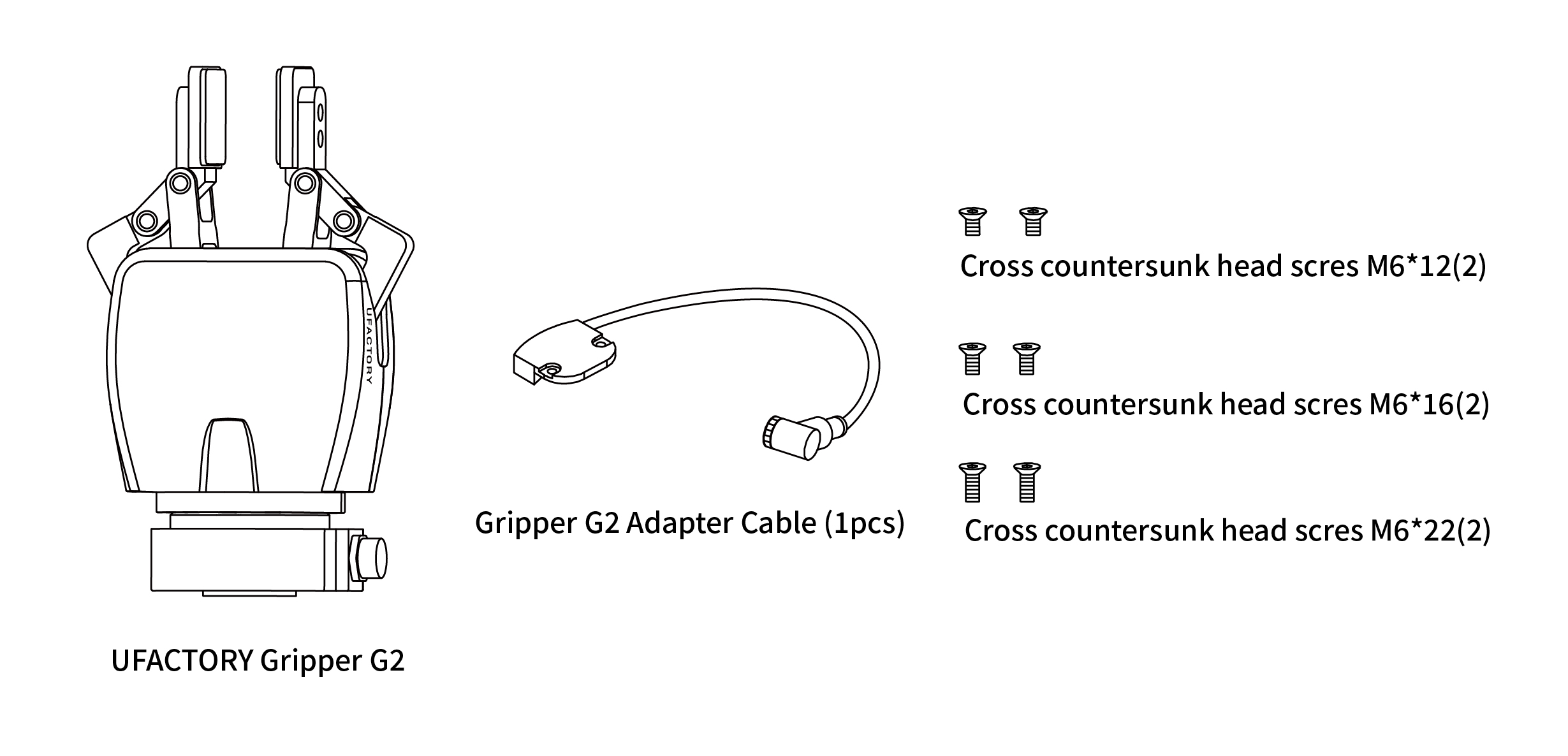
The Gripper G2 kit typically includes the following items (as shown in the figure below):
- UFACTORY Gripper G2 (1 unit)
- Gripper G2 adapter cable (spare)
- Cross recessed head screw M6*12 (2 pcs)
- Cross recessed head screw M6*16 (2 pcs)
- Cross recessed head screw M6*22 (2 pcs)
2.2. Mechanical Installation
2.2.1 Installation Preparation
- Move the robotic arm to a safe position (avoid contact with the installation surface or other equipment);
- Power off the robotic arm (press the emergency stop button on the controller);
2.2.2 Installation
For contact-type arm ends (UF850, XX1305):
Secure the gripper to the robotic arm end using 2 M6 screws.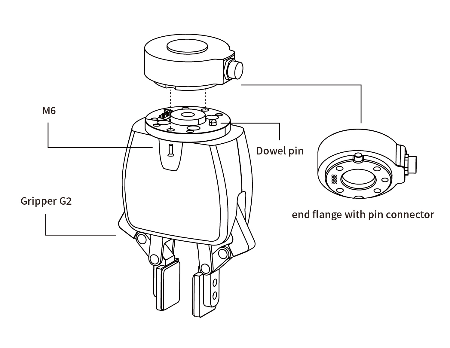
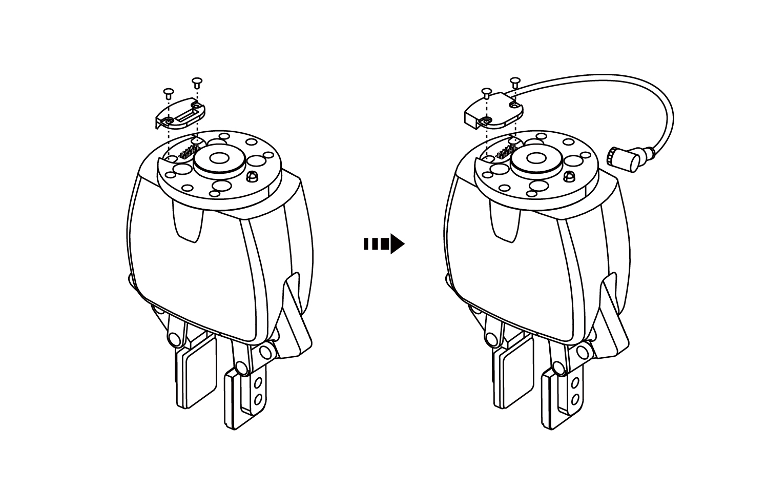
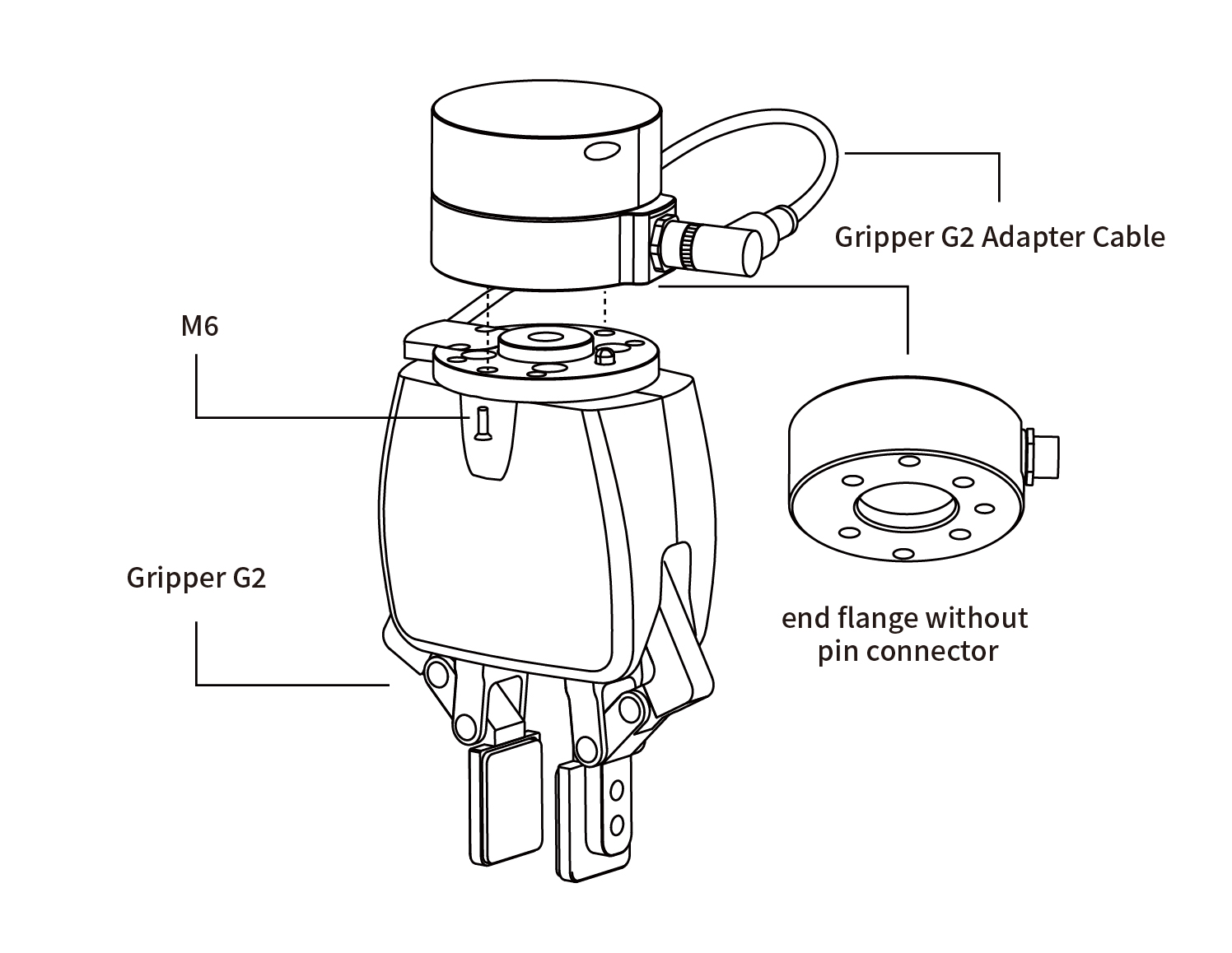
For non-contact-type arm ends (XX1304 or below):
- Remove the two screws on the Gripper G2 flange, take off the black cover, and replace it with the silver cover and Gripper G2 adapter cable;
- Secure Gripper G2 to the robotic arm end using 2 M6 screws;
- Connect the Gripper G2 adapter cable to the robotic arm end.
- Remove the two screws on the Gripper G2 flange, take off the black cover, and replace it with the silver cover and Gripper G2 adapter cable;
CAUTION:
- Always power off the robotic arm during Gripper G2 installation. Ensure the emergency stop button is pressed and the power indicator is off to prevent failures caused by hot-plugging.
- When connecting Gripper G2 to the robotic arm, ensure alignment of positioning holes on both interfaces. The male pins on the Gripper G2 cable are delicate – avoid bending them during installation/removal.
2.3. Electrical Setup
2.3.1 Contact-Type Interface
Contact-type interface definition: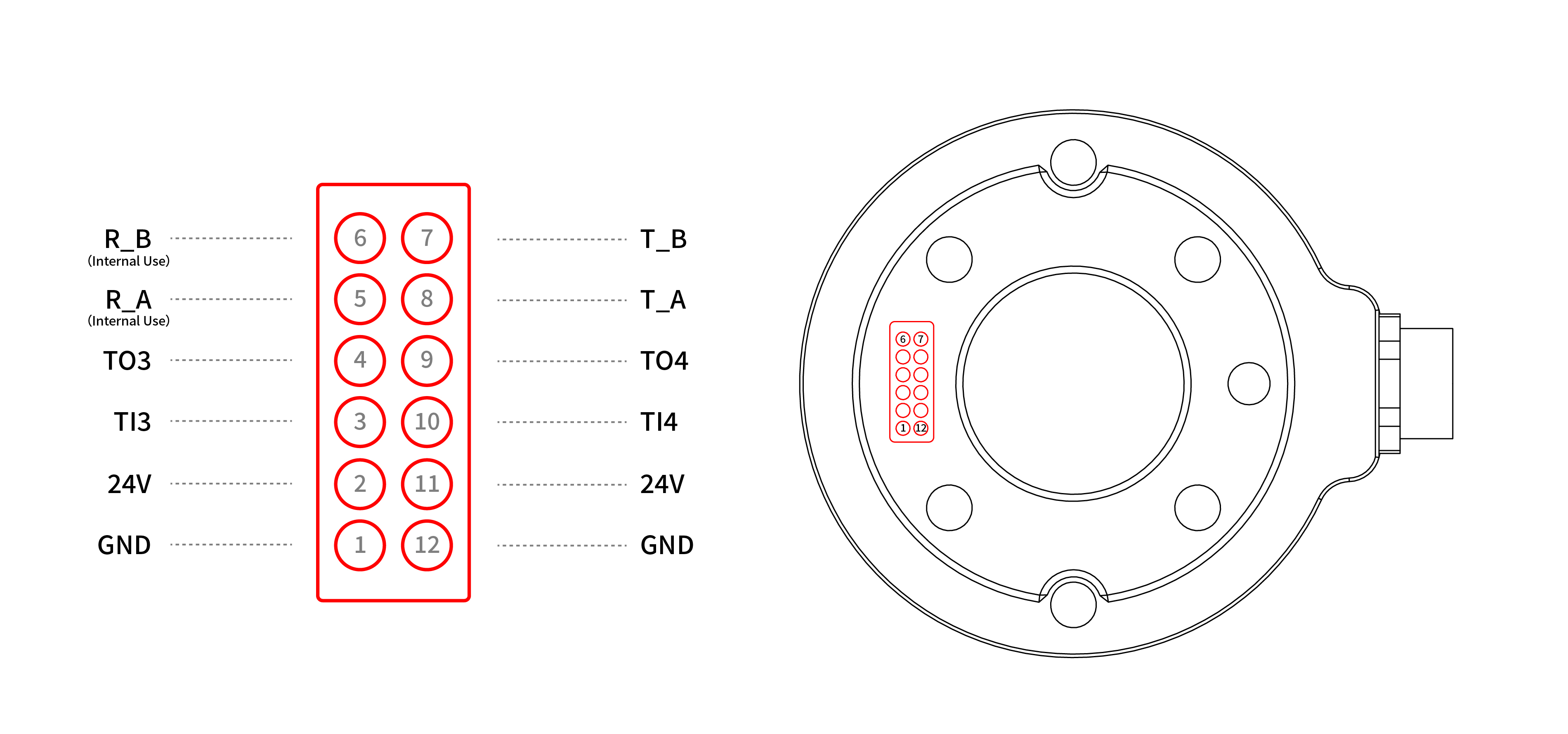
Signals used by Gripper G2: Two 24V, two GND, T_A, T_B.
2.3.2 Aviation Plug Interface
The Gripper G2 aviation plug interface is shown below.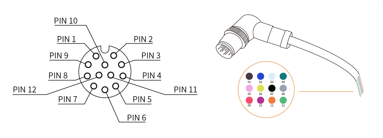
The 12 wires inside the cable have different colors representing different functions. Refer to the table below:
| Pin | Color | Signal |
|---|---|---|
| 1 | Brown | +24V (Power) |
| 2 | Blue | +24V (Power) |
| 3 | White | 0V (GND) |
| 4 | Green | 0V (GND) |
| 5 | Pink | User 485-A |
| 6 | Yellow | User 485-B |
| 7 | Black | Tool Output 0 (TO0) |
| 8 | Gray | Tool Output 1 (TO1) |
| 9 | Red | Tool Input 0 (TI0) |
| 10 | Purple | Tool Input 1 (TI1) |
| 11 | Orange | Analog Input 0 (AI0) |
| 12 | Light Green | Analog Input 1 (AI1) |
Signals used by Gripper G2: 24V (PIN1 and PIN2), GND (PIN3 and PIN4), 485A (PIN5), 485B (PIN6).