2.Installation
2.1 Delivery List
The 6 Axis Force Torque Sensor Kit generally includes these items:
(Please refer to the packing list for the actual items shipped)
- 6 Axis Force Torque Sensor *1
- Mounting Flange *1
- 1300 Mounting Flange *1
- Ft sensor communication cable *1
- Signal Hub *1
- Power cable for the Robotic Arm *1
- Communication cable for the Robotic Arm *1
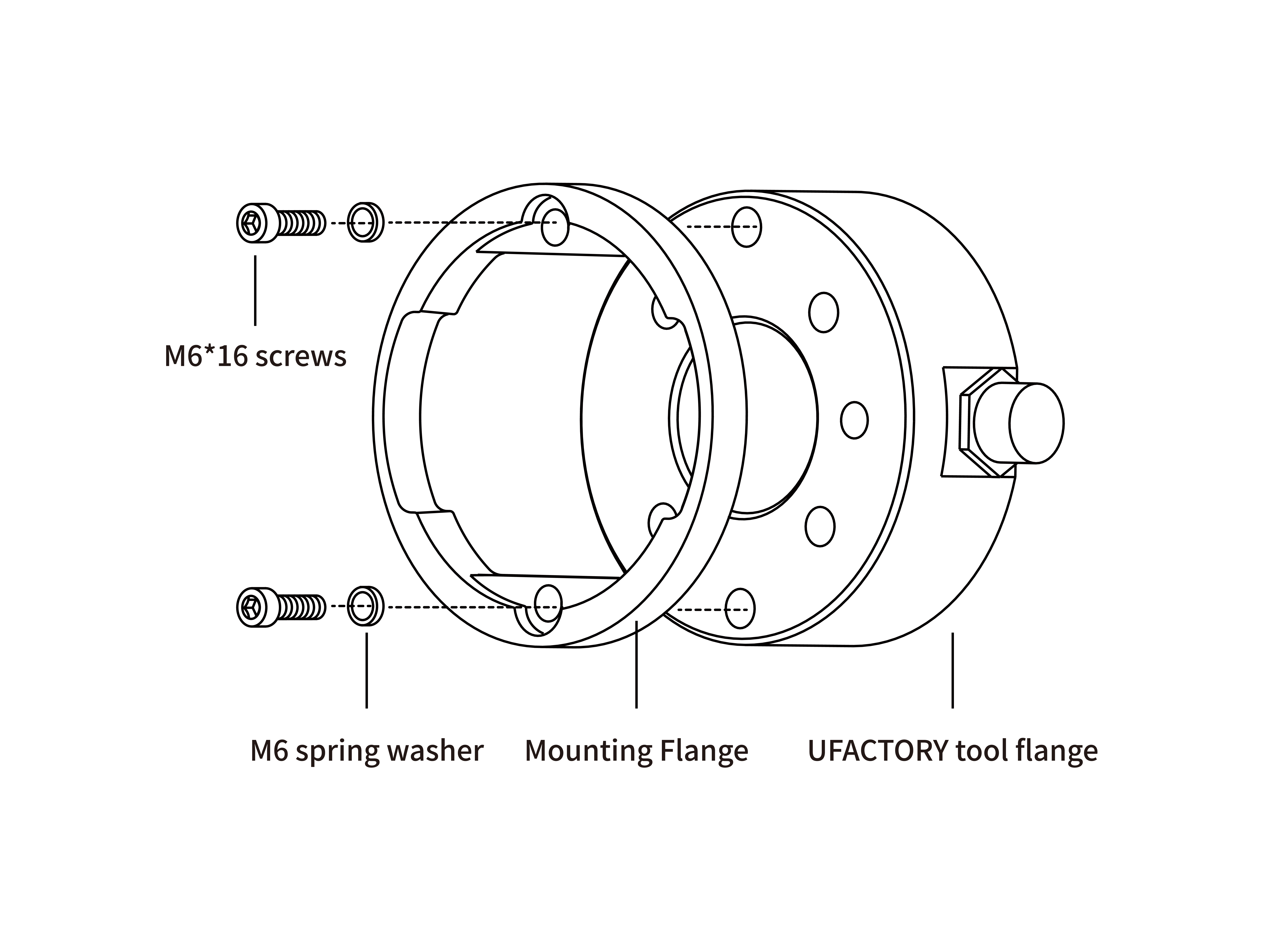
- M6*16 Head hexagon socket screws(2pcs) & M6 spring washer(2pcs)
- M6*20 Head hexagon socket screws(2pcs) & M6 spring washer(2pcs)
- M4*8 Head hexagon socket screws(4pcs) & M4 spring washer(4pcs)
- Velcro(3 meters)
- 2.5MM(1pcs) & 5MM(1pcs) L type wrench
2.2 Mechanical Installation
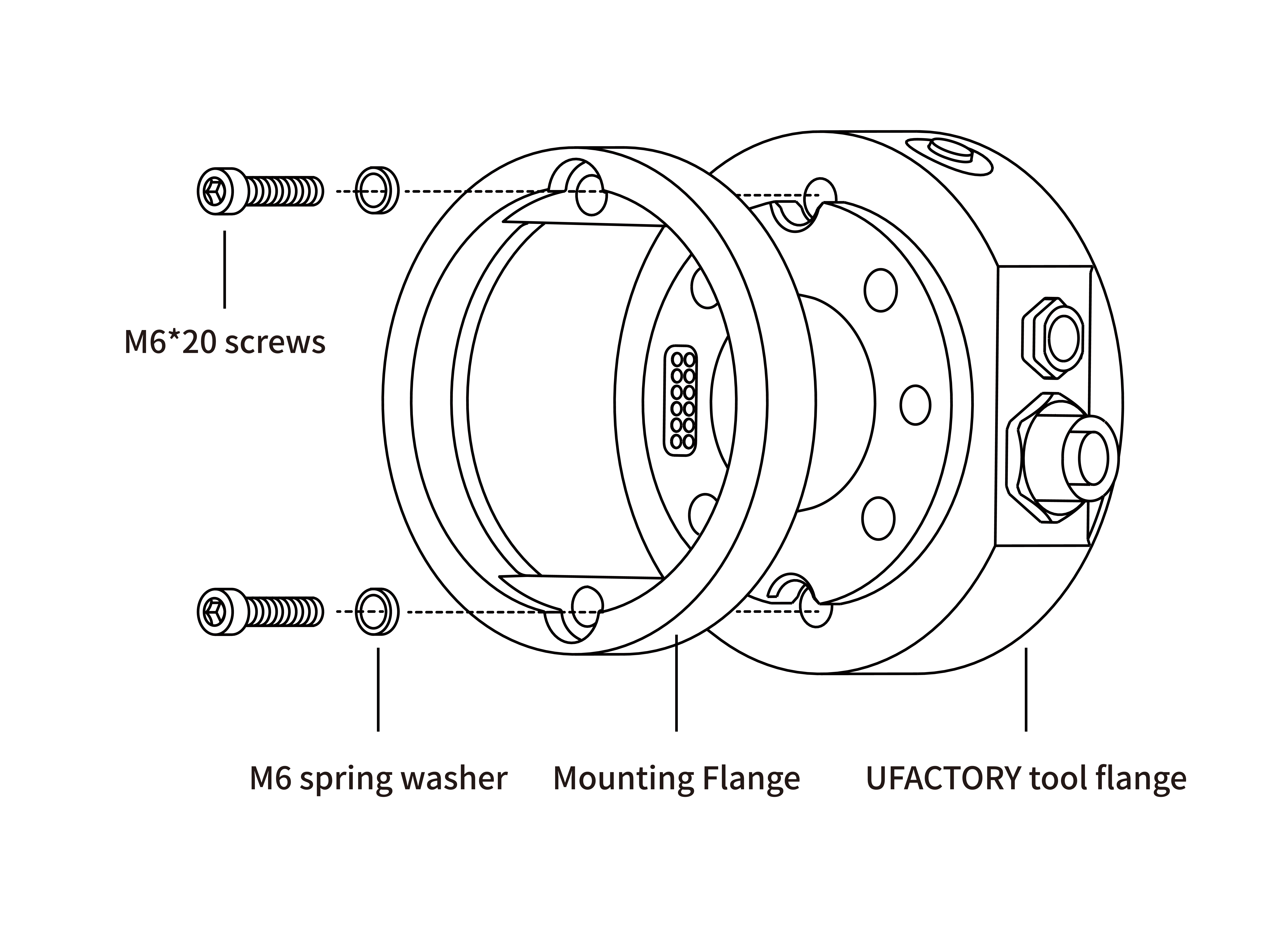
2.2.1 For pin contact(pogo pins) connection(UF850,XX1305)
- Press down the E stop button on the control box.
- Install the Mounting Flange on the end flange using 4 M6*20 screws(spring washer must be used together).
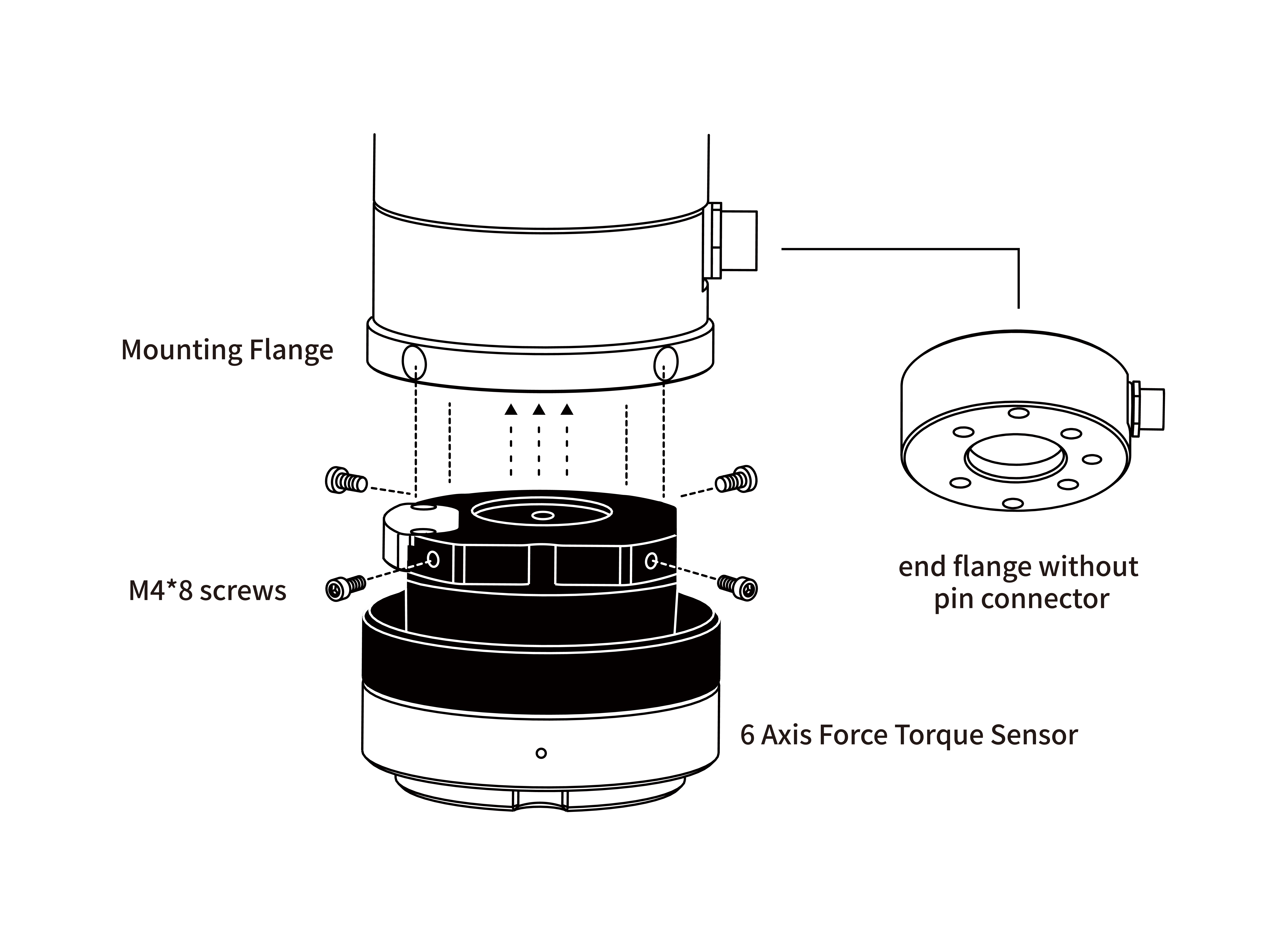
- Install the 6 Axis Force Torque Sensor on the Mounting Flange using 4 M4*8 screws(spring washer must be used together).
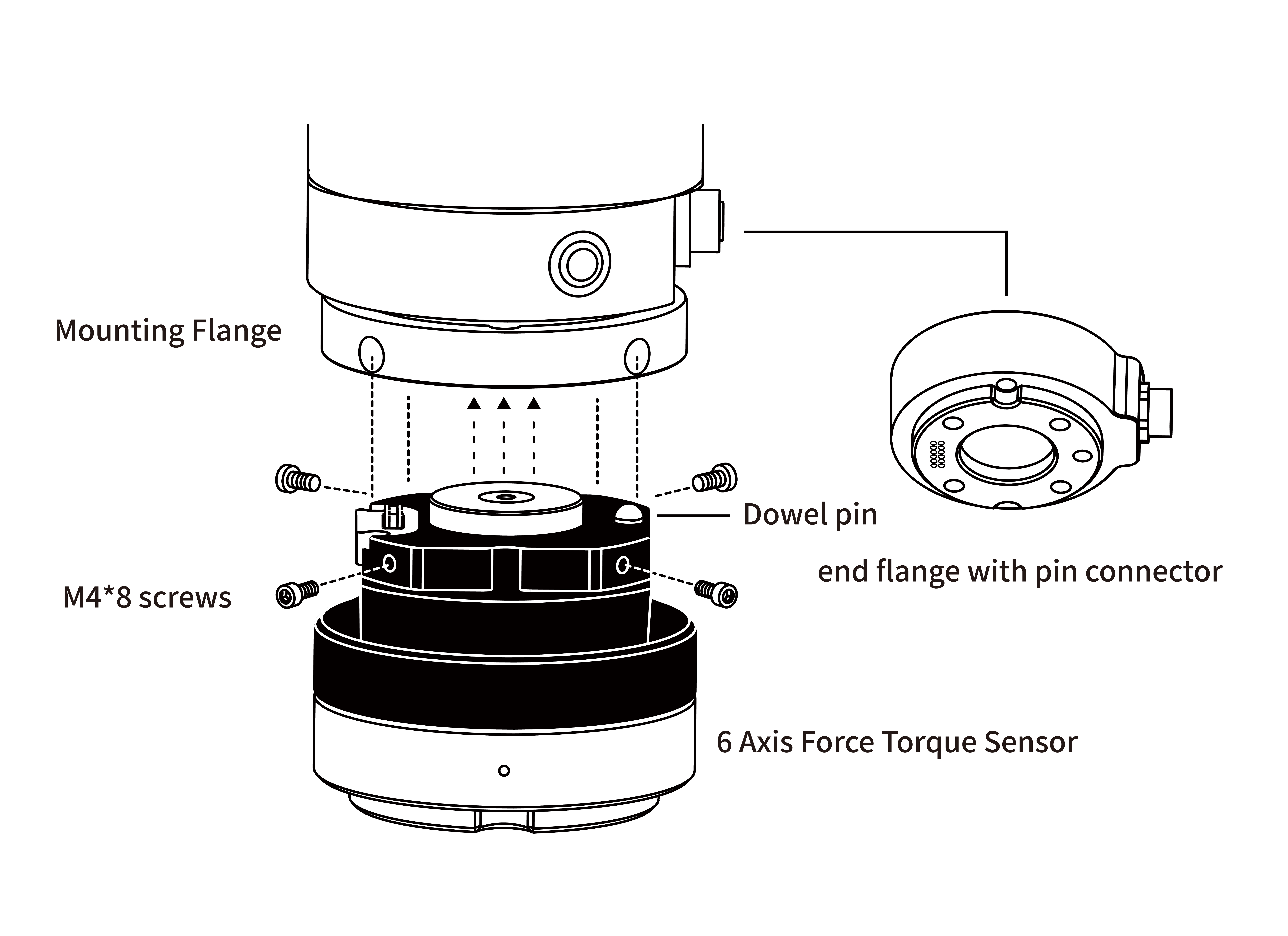
- Press up E stop button on the control box.
2.2.2 For Plug-in connection(XX1304 or below)
- Press down the E stop button on the control box.
- Remove the 2 screws on the force sensor flange, take off the black cover, and replace it with the one that have a signal cable.
Take off the positioning dowel and positioning piece.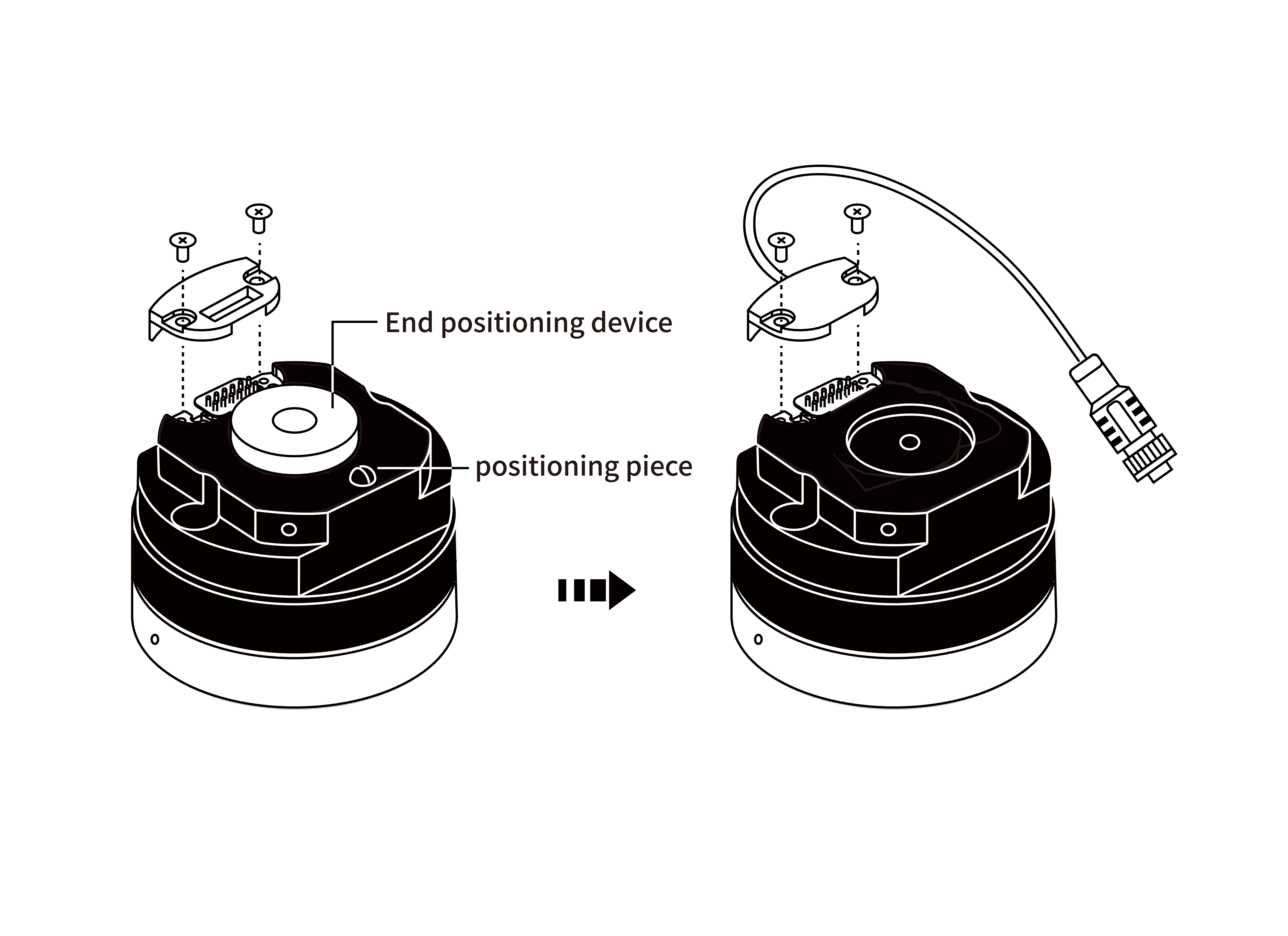
- Install the Mounting Flange on the end flange using 4 M6*16 screws(spring washer must be used together).
- Install the 6 Axis Force Torque Sensor on the Mounting Flange using 4 M4*8 screws(spring washer must be used together).
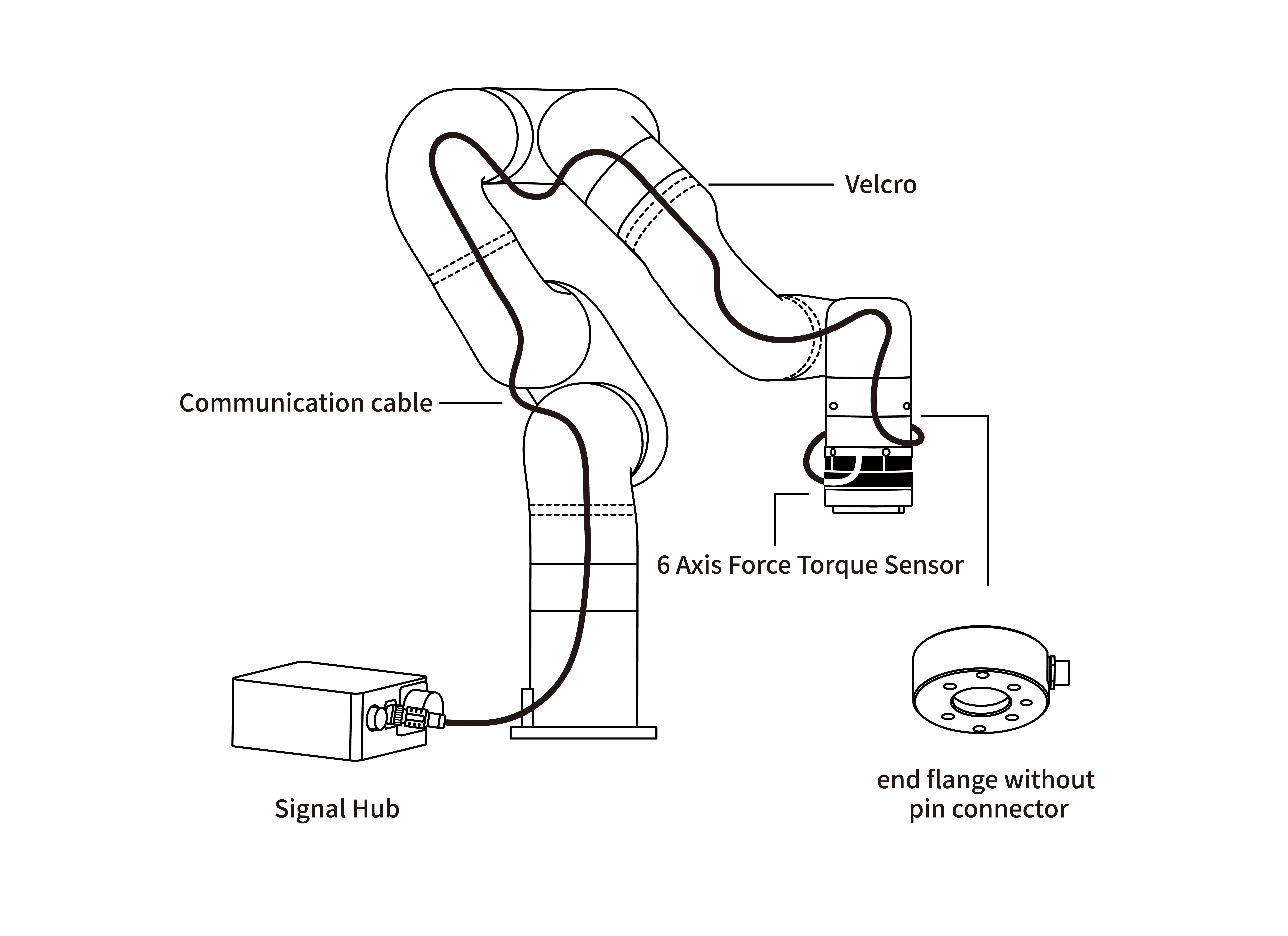
- Connect the 6 Axis Force Torque Sensor communication cable to the signal hub.
2.3 Electrical settings
2.3.1 Pin Contact End Flange
The 6 Axis force torque sensor operates at 24V, GND, R_A, R_B, with a power consumption of less than 2.5W. 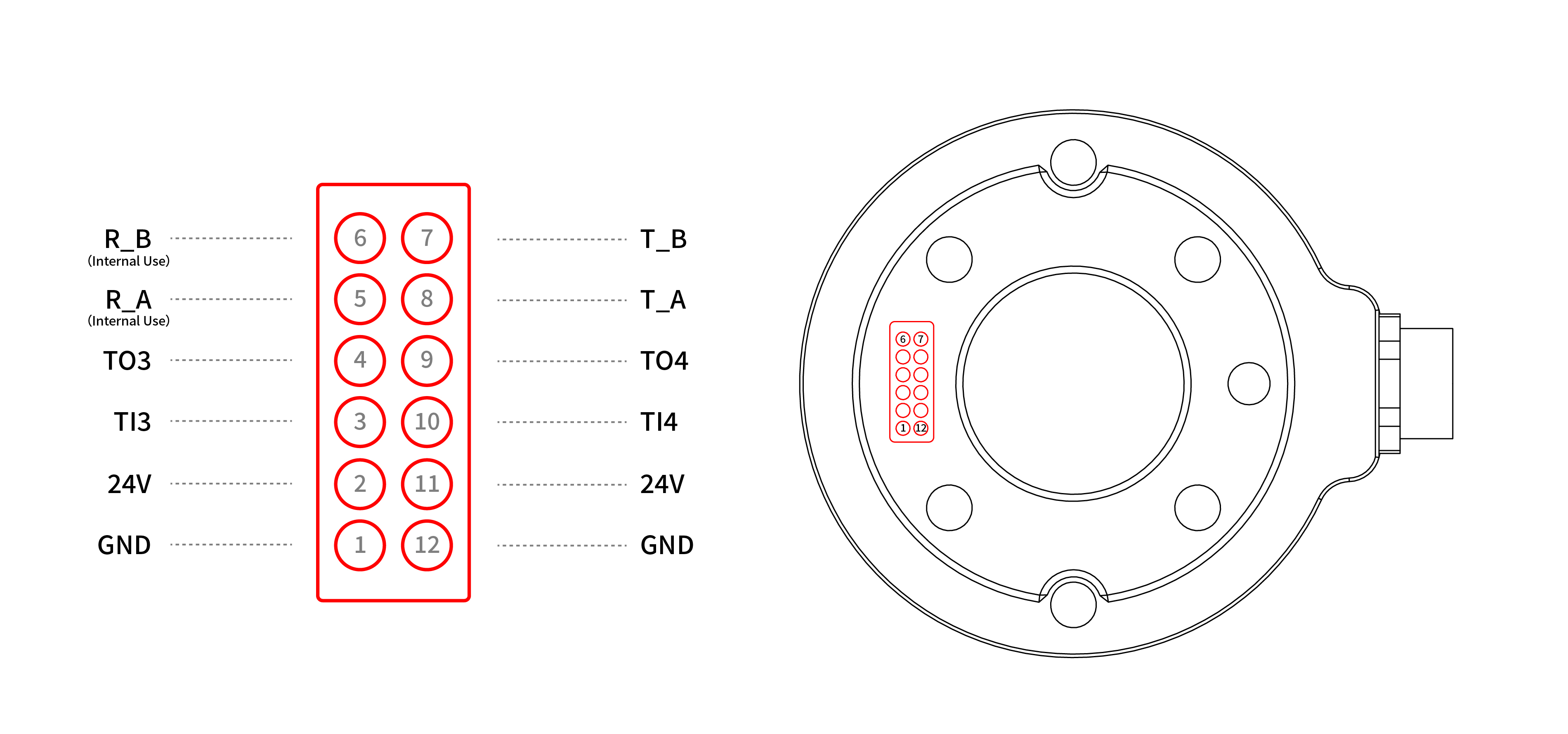
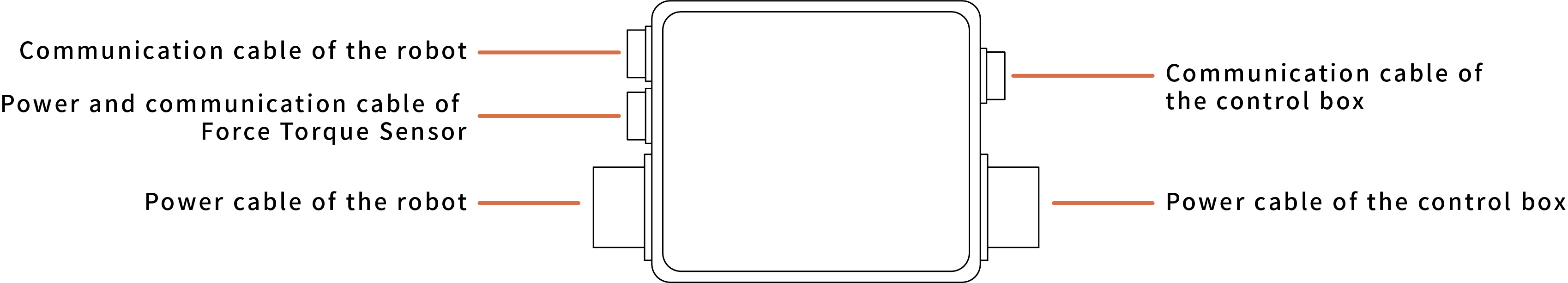
2.3.2 Signal hub
For the robotic arm 1304 or below version, need to use the signal hub to build the communication.